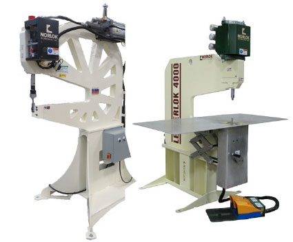
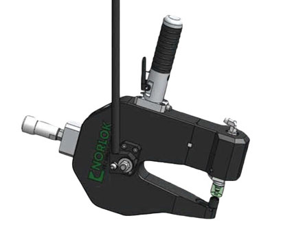
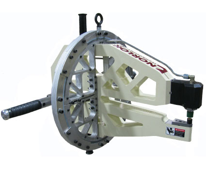
What is Clinching?
Fasten sheet metal without predrilled holes or riveting at a lower cost.
What is Clinching?
Fasten sheet metal without predrilled holes or riveting at a lower cost.
How does clinching work?
Clinching describes the forming of a Clinchlok joint. A Clinchlok joint is formed when the upper tooling squeezes the two ply of material joined between a punch and die. The strength of the Clinchlok joint and the life expectancy of the punch and die are both determined by the amount of squeeze. It is important to note that because the die is of a very special design, the Clinchlok is able to “mushroom”. Like the die, the punch in a Clinchlok joint is also of a special design that has a rounded edge, rather than a sharp edge like a normal punch. This rounded edge is known as the punch tip radius. To form a Clinchlok joint, neither the punch or die can be sharpened.

Upper tooling is used to form a robust Clinchlok joint by precisely
squeezing the two plies of material between a punch and die.
Upper tooling is used to form a robust Clinchlok joint by precisely squeezing the two plies of material between a punch and die.
If different thicknesses are to be joined in a Clinchlok, best results occur when the thicker material is on the upper (punch) side of the two ply but this material should not be more than twice the thickness of the thinner material. The combined thickness of the two ply should not exceed the combined maximum thickness recommended for the die.
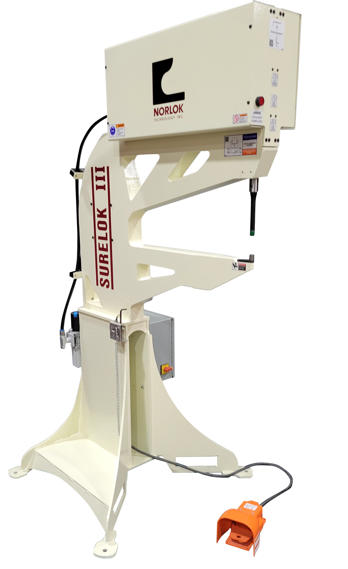
Clinchlok joints made of other materials can be joined with our SURELOK II machine as long as the materials are not harder than commercial quality mild steel. In most cases both ply should be of the same hardness. If a different hardness is used for each ply (not recommended) the harder material should be on the upper (punch side), if possible.
What are the advantages
of clinching?
Joint Strengths
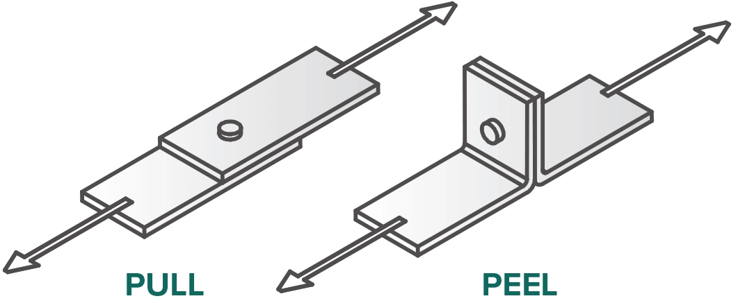
There are two ways to measure the strength of a Clinchlok joint – pull and peel. The pull joint is almost always stronger than peel joint and is less sensitive to die adjustment.
Please refer to the chart below for typical joint strengths for various commercial materials. These should be used only as a guide. Different materials will affect the joint strength. If the material is softer than mild steel these strengths will be reduced according to the strength of the material.

Light Duty – 0.12” (3.0mm) Round or [Not Available in Rectangular]
Light Duty – 0.12” (3.0mm) Round or [Not Available in Rectangular]
Medium Duty – 0.18” (4.6mm) Round or 0.12” (3.0mm) Rectangular
Medium Duty – 0.18” (4.6mm) Round or 0.12” (3.0mm) Rectangular
Heavy Duty – 0.25” (6.4mm) Round or 0.18” (4.6mm) Rectangular
Heavy Duty – 0.25” (6.4mm) Round or 0.18” (4.6mm) Rectangular
Mild Galvanized Steel:
Scroll left and right to view table.
| Mat. Thickness (each, 2-ply) inch [mm] |
Strength (Pull) lbs [N] |
Strength (Peel) lbs [N] |
Recommended Die |
|---|---|---|---|
| 0.012″ (32g) [0.30] | 120 [534] | 15 [67] | #20 |
| 0.016″ (30g) [0.41] | 150 [667] | 18 [80] | #20 |
| 0.019″ (28g) [0.67] | 165 [734] | 20 [89] | #25 |
| 0.022″ (26g) [0.56] | 180 [801] | 25 [111] | #25/#30 |
| 0.028″ (24g) [0.71] | 200 [890] | 30 [133] | #30 |
| 0.022″ (26g) [0.56] | 285 [1268] | 70 [311] | #30 |
| 0.028″ (24g) [0.71] | 325 [1446] | 85 [378] | #30/#40 |
| 0.034″ (22g) [0.86] | 375 [1668] | 100 [445] | #40 |
| 0.040″ (20g) [1.02] | 400 [1779] | 120 [534] | #40/#50 |
| 0.052″ (18g) [1.32] | 430[1913] | 150 [667] | #50 |
| 0.063″ (16g) [1.60] | 475 [2113] | 175 [778] | #50 |
| 0.028″ (24g) [0.71] | 550 [2447] | 190 [845] | #40 |
| 0.040″ (20g) [1.02] | 600 [2669] | 200 [890] | #40 |
| 0.052″ (18g) [1.32] | 700 [3114] | 220 [979] | #40/#50 |
| 0.063″ (16g) [1.60] | 800 [3559] | 250 [1112] | #50/#60 |
| 0.080″ (14g) [2.03] | 1000 [4448] | 300 [1334] | #60 |
| 0.105″ (12g) [2.67] | 1200 [5338] | 400 [1779] | #70 |
| 0.138″ (10g) [3.51] | 1400 [6228] | 500 [2224] | #70/#80 |
Aluminum:
Scroll left and right to view table.
| Mat. Thickness (each, 2-ply) inch [mm] |
Strength (Pull) lbs [N] |
Strength (Peel) lbs [N] |
Recommended Die |
|---|---|---|---|
| 0.032″->0.032″ [0.81 ->0.81] | 160 [712] | 55 [245] | #30 |
| 0.040″->0.040″ [1.02 ->1.02] | 175 [778] | 60 [267] | #40 |
| 0.050″->0.050″ [1.27 ->1.27] | 260 [1157] | 85 [378] | #40 |
| 0.063″->0.063″ [1.60 ->1.60] | 240 [1068] | 72 [320] | #40 |
| 0.080″->0.080″ [2.03 ->2.03] | 265 [1179] | 90 [400] | #50 |
| 0.090″->0.090″ [2.29 ->2.29] | 225 [1001] | 150 [667] | #50 |
| 0.063″->0.040″ [1.02 ->1.60] | 270 [1201] | 50 [222] | #40 |
| 0.040″->0.063″ [1.60 ->1.02] | 140 [623] | 45 [200] | #40 |
| 0.063″->0.090″ [2.29 ->1.60] | 210 [934] | 48 [214] | #50 |
| 0.090″->0.063″ [1.60 ->2.29] | 240 [1068] | 95 [423] | #50 |
Stainless Steel Clinching (Rectangular or Lance type)

Clinching stainless steel typically requires the use of a rectangular clinching type, that is often referred to as “Lance” clinching. The Lance tooling option is available on most machines, and involves very accurate alignment concentrically, but also in the parallel direction. Typical strengths, in pounds, for stainless steel.
Scroll left and right to view table.
| Mat. Thickness |
Transverse (Pull) lbs [N] |
Parallel (Pull) lbs [N] |
Transverse (Peel) lbs [N] |
Parallel (Peel) lbs [N] |
Recommended Die |
|---|---|---|---|---|---|
| 18g | 1080 [4804] | 590 [2624] | 180 [801] | 215 [956] | #60 |
| 20g | 650 [2891] | 520 [2313] | 85 [378] | 95 [423] | #50 |
| 22g | 430 [1913] | 380 [1690] | 75 [334] | 90 [400] | #50 |
| 24g | 340 [1512] | 270 [1201] | 40 [178] | 50 [222] | #40 |
Testing Joint Strengths
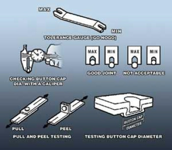
The best method of testing joint strength is to pull the joint apart in both pull and peel as well as measure the force required with a pull tester. In production, however, an indication of the joint strength can be found by measuring the diameter of the button cap (the “mushroom”) on the die side of the joint. If a joint is tested in pull and peel with a pull tester and the upper and lower limits of joint strength are found, the cap diameters for these two limits can be measured. Callipers or a GO-NOGO gauge can then be used in production to see if the cap diameter is within the measured limits. If the material changes or the die number is changed, the cap diameters will change. When using the button cap, diameter shear and peel tests should also be used occasionally to confirm strengths.
Due to the overwhelming number of possible button diameters (various thicknesses, various gauge of material, etc.) Norlok does not typically supply these devices. The best method is to determine the acceptable joint strength for your particular application and to fabricate one for yourself. Norlok can be of assistance in determining ideal pull strengths if required.

